
Howdy, Stranger!
It looks like you're new here. If you want to get involved, click one of these buttons!
Here's what I've compiled so far on how to get the PMH to cough up electricidaaddy

Greetings folks, first time coming out of lurking mode after trolling all you mad geniuses mfkers posts since before Bill Gates unleashed Plandemic 1.
Alright here are some of my findings:
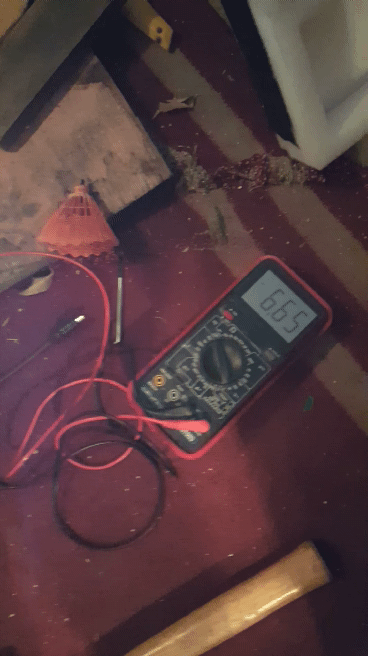
The PMH has 4 lines of flux going, and they line up in a circle SNSN in the keeper. According to my digital meter, it \s it seems the 2 coils like ingesting no more and no less than 10.6 volts DC and about 5 amps according to my analog voltage source readout on the amps side.
If you rotate the polarity of the coils quickly and/or oscillate the voltage level input, you give the flux a 'curve' so the electrical field also moves, and moves to get the coil around the keeper to start outputting AC. I was goofing around and I hookedup the keeper coil back into the circuit with the other ones while just spamming the rotary voltage level control, and somehow my meter started reading straight 6.6666 volts in ... AC mode. Im gonna try to rotate it by sneaking a 1mm thick magnetic flywheel in a flux air gap somewhere, I saw tesla was using a similar approach for his dynos, but he used a 2-plied copper wheel with voltage inputs on both sides to create a magnetic field in the flux air gap (about 3mm or less).
The circuit seems to be a couple of PMH attached to a transformer core, and you use a commutator/oscillator/magnetic spinner to get the flux to rotate and create current in the coils. Looks like high voltage on one side creates high current on the other, which is why i think he cannibalized everything from a MODEL T, including the flywheel, crankshaft, induction coil, commutator, etc.
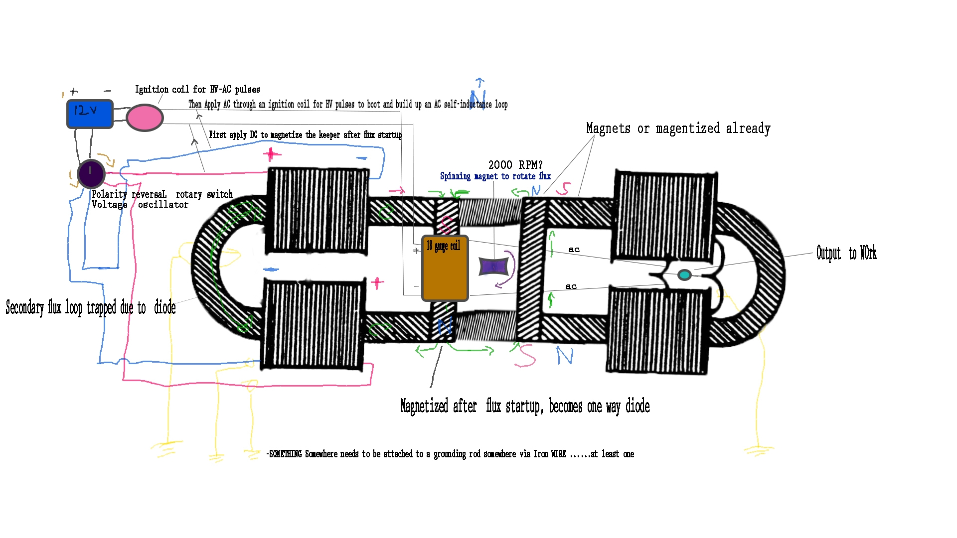
So while I'm going through the various options, I made a schematic of what i THINK is one viable option to get it to 'work' as a domestic-home-made-current-generator. Still experimenting. Waiting for a commutator switch to show up.
So, here's my take, see diagram:
Start the flux in the usual way, activate 2nd pmh (female) on the other side, with a magnetized u-body and keeper in the other direction, run DC through the daddy PMH keeper coil to magnetize the daddy keeper and give the 'outward going' flux a single way to go and keep it in the 'transformer core middle ground', then hook up the car ignition coil to the daddy coil, connect the daddy coil with the female pmh coils, and run HV AC current with a small motor that turns a magnet in the transformer core, keep energizing everything until uhm.... something somewhere starts to read an output that is... likeable... and start looping your power to where its needed and then .... charge your phone and call your mom.
One thing that ED mentioned is to spin the magnet at 2,000 RPM, which in Hertz is 33.3333, which is 16.666 x 2... (100/6 = 16.666.
The pmh is 33 in length (33x2= 66, needs... 6 to get to.. 72 (2 circles = 36 x 2 - double magnetic torus)... and 6 is in the keeper....oh wow, how... convenient...
Another thing is that on his PMH diagram,I noticed there's 26 lines for the keeper going one way, and 35 for the u-bar the other way.
Also, like RL Poole discovered with his diagram overlay, if you take that magnetic symbol from the other book and connect it like he has it displayed, it runs along that secondary flux loop trapped in the back arch, and... probably down into a couple of grounding rods (iron wire, induction, not electric) so it makes sense so far how to re-supply the flux reservoir.
Keep the feedback going you mad lads ands lade-ttes and attack helicopters and defensive locomotives you! Oh, and next time I can tell you how 5G can be a giver AND/OR taker of corona (or any) pathogen, why they want 6 feet away, aaand...how its all related to the magnetic torus. (thanks Bill Gates, I couldnt have figured out the PMH without your plandemic activation of protocol666)
cheers!
-Dracul
Powered by leedskalnin.com & buzzdev.net
Comments
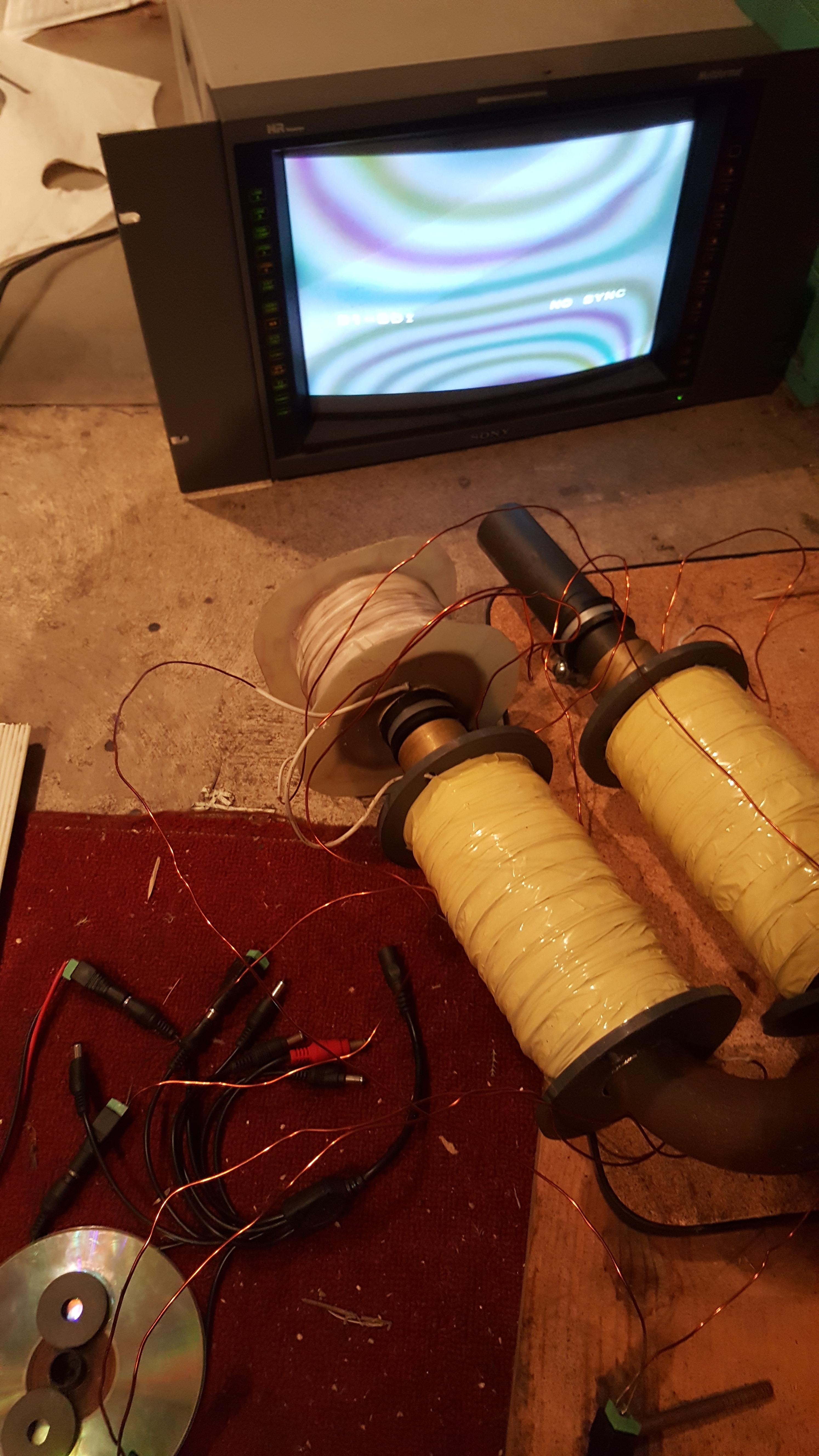
lol, I think I recognize that unit, is that you antman, you old devil?
or is the flux the white area in between them...?
It looks like its because the monitor has 3 electron guns, one for each color. The inverted rainbow effect is perhaps caused by the opposing polarities of the PMH prongs: https://www.physlink.com/education/askexperts/ae521.cfm
Ah thank you, that should cover it. The flux is prying the 3 color-electron-guns from achieving convergence at the screen phosphorus point