
Howdy, Stranger!
It looks like you're new here. If you want to get involved, click one of these buttons!
I figured out how the magnetic current flows

I figured out how magnetism flows
I learned this from vertically spinning magnetic shavings in a box along the edge.
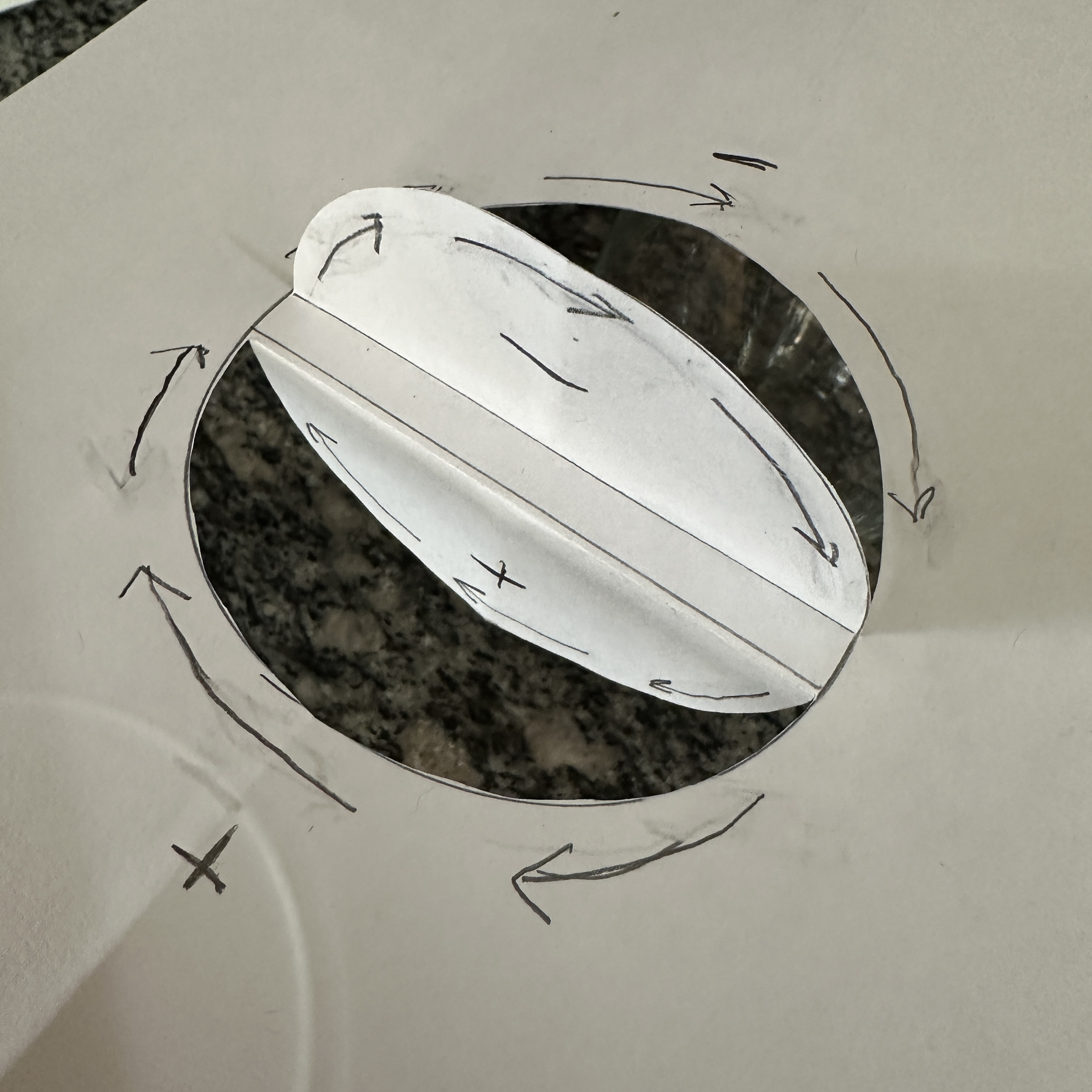
Half the shavings spinning left, up, and over the side of the box in a vertical spinning motion causing the shavings to follow a path that goes upward and then arcs over the side of the box pushing the shavings along the ground plane. Creating an upward and then downward loop in the magnetic field lines.
Polarity and Rotation: If the magnet is spinning, one pole (north or south) coming towards you would push shavings away (right or left depending on polarity), and the opposite pole moving away from you would pull them back. The vertical lift could be due to the magnetic field lines arching up and then down over the magnet.
Visual Effect: akin to a combination of a Ferris wheel (for the vertical motion) and a conveyor belt (for the horizontal motion), where the shavings are being influenced by both vertical and horizontal components of the magnetic field.
Looks like the same structure of a black hole

I learned this from vertically spinning magnetic shavings in a box along the edge.
Half the shavings spinning left, up, and over the side of the box in a vertical spinning motion causing the shavings to follow a path that goes upward and then arcs over the side of the box pushing the shavings along the ground plane. Creating an upward and then downward loop in the magnetic field lines.
Polarity and Rotation: If the magnet is spinning, one pole (north or south) coming towards you would push shavings away (right or left depending on polarity), and the opposite pole moving away from you would pull them back. The vertical lift could be due to the magnetic field lines arching up and then down over the magnet.
Visual Effect: akin to a combination of a Ferris wheel (for the vertical motion) and a conveyor belt (for the horizontal motion), where the shavings are being influenced by both vertical and horizontal components of the magnetic field.
Looks like the same structure of a black hole
Powered by leedskalnin.com & buzzdev.net
Comments
I found the speed of the spinning magnet interesting. At low speed you can see how the iron sand aligns and does cart wheels on the glass table. At faster speeds the ridges appear and excess sand is deposited around the inner and outer rim of the magnets. \, |, /. I never really paid much attention to the burms of sand around the rims, other than notice one end of the burm sand was being added and the other end the sand was being removed. The burms seem to travel in the direction of the flywheel while the sand over the magnets travels the opposite direction of the flywheel.
@Heyjoe I think we are all saying the same thing just using different words to explain what our eyes see.
@Magnetic_Universe I noticed that when the drill is turning clockwise beneath the paper box and shavings, it is actually spinning counterclockwise since it is upside down. Consequently, the shavings rotate in the opposite direction, which is clockwise. However, if I reverse the drill to appear to turn clockwise from underneath, the shavings will continue to spin in the same clockwise direction.
If I position the drill to spin vertically and use it on the corner of the paper box, the rotation of the shavings is affected. Half of the shavings rotate in a clockwise direction along the plane, while the other half rise and move in a counterclockwise direction. half pulled, half pushed.
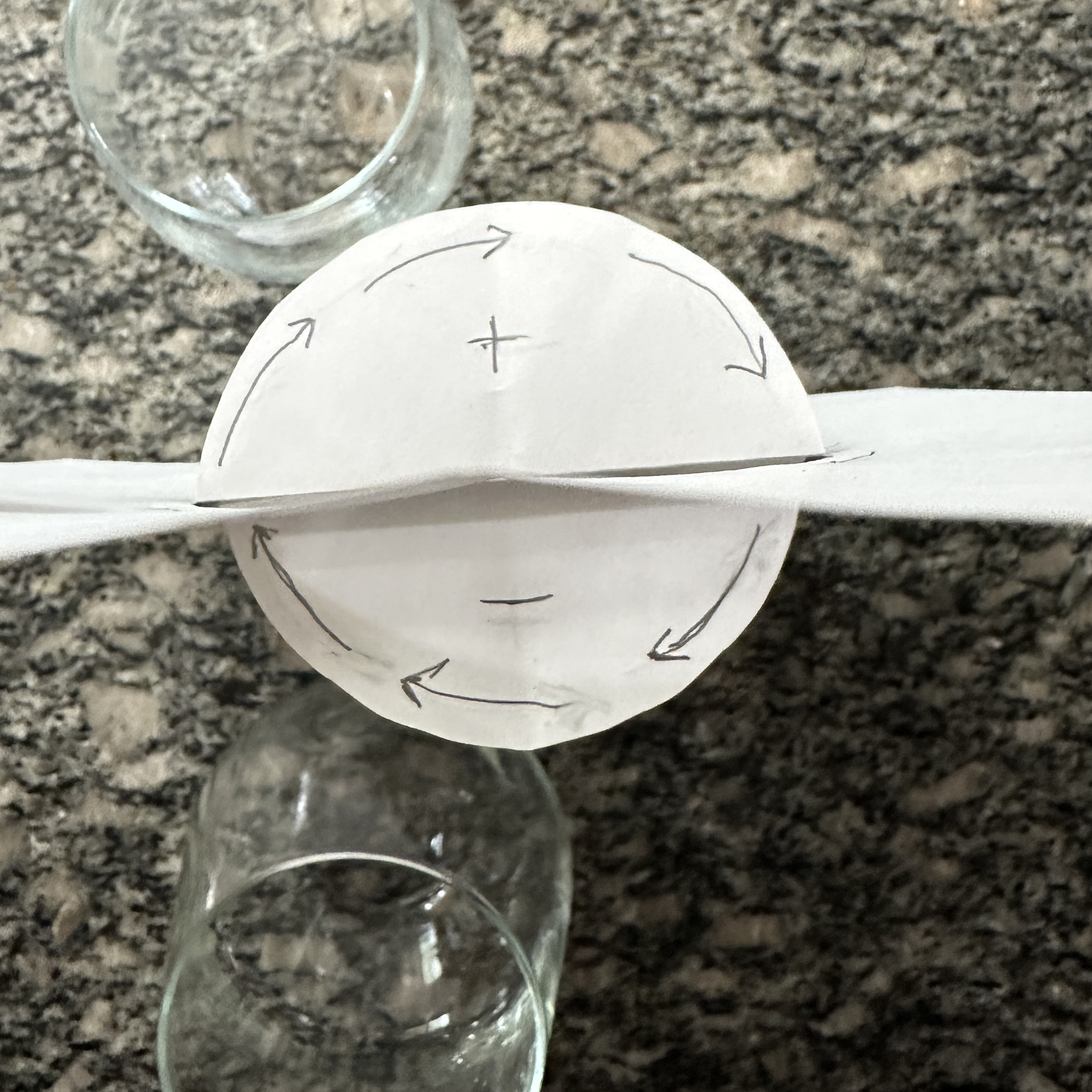
This indicates to me that a full magnetic cycle doesn't spin in a horizontal circle; instead, the North spins half a circle from left to right, while the South spins the other half from up and over, right to left.
So it seems to me that the two magnetic currents are oscillating at a Horizontal & Vertical Frequency.
According to ED's calculation for 2000 RPM, we divide 2000 RPM by 60, which results in 33.33 Hz. This frequency corresponds to an Alnico magnet with a dual-pole magnet (e.g., bar magnet with North on one end, South on the other, or a ring with two North-South pairs) rotating side to side within the PMH Each 33.3 Hz rotation passes two pole pairs (North-South, South-North) by each coil triggering two cycles. 66.6 Hz induced voltage per leg. Two flows (33.3 Hz and 66.6 Hz) in the PMH orbit could sustain perpetual motion, hitting the 99.9 Hz harmonic via combined action along the bridge and 3rd coil. (crossbar)
1st harmonic = 33.3 Hz.
2nd harmonic = 66.6 Hz.
3rd harmonic = 99.9 Hz.
Align phases—33.3 Hz spin (spin), 66.6 Hz leg coils (induced), 99.9 Hz bridge coil (pulsed by the induced coils and spin)—all peak together harmonizing the system at the 3rd harmonic.
A 12 volt dc motor is how I was turning the magnets on my turn table. Dimmer switch to the transformer gave me speed control. The flywheel is 36 magnets total. 18 on top and 18 on the bottom. 1 inch round, 1/4 inch thick magnets spaced 1 inch apart. There is a 1/8 inch gap between the top and bottom magnets in attraction. North space South space north....
I hung the string from a bent wire I magnetized in an S shape similar to what ED illustrates on the first page of his Magnetic Current book. It is an off-center point shape, meaning the string hangs off its center of gravity. Doesn't seem to work as well if I hang it off a perfectly balanced S hook or straight point. What I think is happening, since it is unbalanced, is that the north pole of the magnet hanging on the south side is sitting in the center of gravity line and getting pushed out. When I hang a second magnet, I inverted the 2nd S hook and spaced them appropriately apart, they start to alternate and interact with each other, one alternates and makes the other spin. Then it switches, taking turns to alternate and spin.
I still want to time the rhythm and see how many alternations it does per minute, etc..
So my idea is to try and use this alternating hanging magnet to mimic ED's sample with his swinging 3rd coil to possibly get electricity or magnetic flow from it through two coils on the side. Any metal around will disrupt the swing, so I need to use copper to draw out the current. Any ideas how I can try this?
I was thinking to accomplish something like this with the alternating hanging movement. https://imgur.com/gallery/magnetic-coupling-motion-H1a1Grl
@Magneticus_Attractus Can I see a picture of your magnetic generator?
What do you think Ed meant when he said, "without using the winding that the machine uses to increase the strength of the permanent magnet"?
I counted the oscillations of the hanging magnets while they were in my garage. They oscillate 100 times in 60 seconds but eventually stop oscillating @30min - 1 hr.
However, when I placed them outside in the sun between the sun and a shadow line, they didn't stop oscillating. They make a different oscillating pattern and I count 34 cycles every 60 seconds. I have a little video of it here https://imgur.com/gallery/measuring-oscillating-magnet-qVJhP81
I cut 1.5-inch metal rods and positioned them at the center of each edge. Since the edges are neutral, with both poles on the same side, I found that once the magnets magnetized the ends of the rods, they shifted into this position (as shown in my video clip).
The rods are sitting in the same crooked slant as you'll see when you put the 6x 1" fishing line rods on top of the glass in Ed's experiment. I am starting to believe that the free magnets we are all trying to manipulate are located along the neutral point of a magnet. Additionally, they can be tracked based on the "one-half" calculation in ED's dimensions. The 1/2" is the size of the neutral line that separates the poles. In Ed's other example with the 4" permanent magnet raised below the 2 vertical hanging magnetized lines spaced at 3" above, which is 1/2" off on both ends, the magnetic flow pulls in or pushes out. You can see the demonstration here. https://imgur.com/gallery/tracking-magnet-bars-magnetic-flow-looking-current-pull-push-out-WQs44MT
So I believe the "one and one half inch in diameter" PMH bent bar should be a rectangle 1"x1/2" it could be bent 2 ways. The cross bar would be overlapping the prongs
You can see with some of ED's stones placed along or from the edge.
North and South are what make the lights ($$$), so North and South are all that are discussed, nowadays.
If you wrap the middle of a core with wire and charge the wire, a north pole appears at one end of the core, and a south pole at the other.
So where is the Bloch Wall?
"Nothing" happens within the Bloch Wall.
Ed talks about everything except the Block Wall, he demonstrates how the magnets flow around the Block AKA Wire. Follow the path they flow and you will find the corner Block they go around. He tells where that corner is in the wire, if you map out the direction of the currents when you follow his fishing line magnetizing in specific directions. (I think it's in the top right corner)
The secret we are trying to uncover lies in the Block. We haven't provided a path for it to follow the magnetic flow. It should always be positioned in the middle of the poles. Currently, if it's in the spool, it lacks a pathway to reach the other spool or side, leaving both sides moving straight parallel to each other without any attraction.
I mapped out my earlier design better of the PMH cross bar using a 1"x1/2" bent bar, trying to track the BLOCK. Scale is 2 blocks = 1 inch